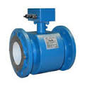
Mecon Electromagnetic Flowmeter
Mecon Electromagnetic Flowmeter
 Feature
- Special lining upon request
- various connection types and materials different materials and process connections
- Flange : DIN, ANSI, JIS
- Clamp
- DIN 11851
- And other upon request
Application
Electromagnetic flow sensor mag-flux A are precision measuring devices, suitable for determining the flow rate of nearly any electrically conductive fluid, but also for substances such as sludge, pulp and paste.
Due to the magnetic field, the device can be used to measure flow rates up to 10 m/s (32.8 ft/s) and a minimum conductinity of 3 ps/cm, when using a synchronized static flield.
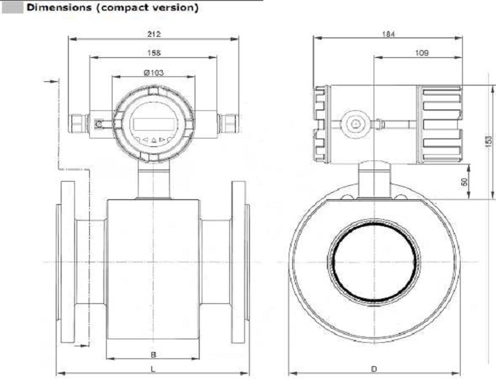
The entire measuring device comprises a flow sensor and a dedicated transmitter. Those can be delivered either separately or as a compact unit.
The electromagnetic flow sensors mag-flux A are applied mainly in the following indudtries :
- Water and sewage plants
- Chemical and pharmaceutical industry
- Food and beverage industry
- Mining, cement and mineral materials
- Pulp and paper industry
- Steel industry
- Energy industry, public utilities
Mode of operation
The units work on the principle of faraday’s law induction, whereby, simply stated, the sensor converts the flow into voltage, propotional to the flow rate.
Special features
- Solid welded steel design, therefore rugged and fail-safe
- signal amplifier inside sensor
- Inside diameter of measuring tube from 15 mm (0.591″)
- pressure up to 250 bar
- Liner :
- hard rubber
- soft rubber
- PTFE
Technical Data
| Application field | see page 1 |
| Measuring principle | Pulsed constant field (DC) |
| Inlet
Nominal diameter Proces Connection
Measuring Accuracy Error of measurement
Repeat accuracy
Operational conditions Direction of installation
Max. operating temperature With rubber lining with PTFE (Teflon) lining
Pressure limits rubber lining PTFE (Teflon) lining Protection class
|
DN 15 – DN 600 ·        DIN 2501 ·        ANSI B 16.5 ·        JIS ·        Table ·        Special connections
± 0,5% of the reading from 0,25 m/s to 10 m/s ± 0,15% of the reading from 0,25 m/s to 10 m/s
see Instalation Instructions on page 2
90C/ 194 F, 100C/ 212F optional 180C (at 16 bar) 150C (at 25 bar) 100C (at 40 bar)
Max. 250 bar Depending on ambient temperature (see above) IP 67/ IP 68
|
| Requirements on the media
Minimum conductivity Max. flow rate Flow rate final value |
>5 S/cm 10 m/s 0,25 – 10 m/s |
| Specifications
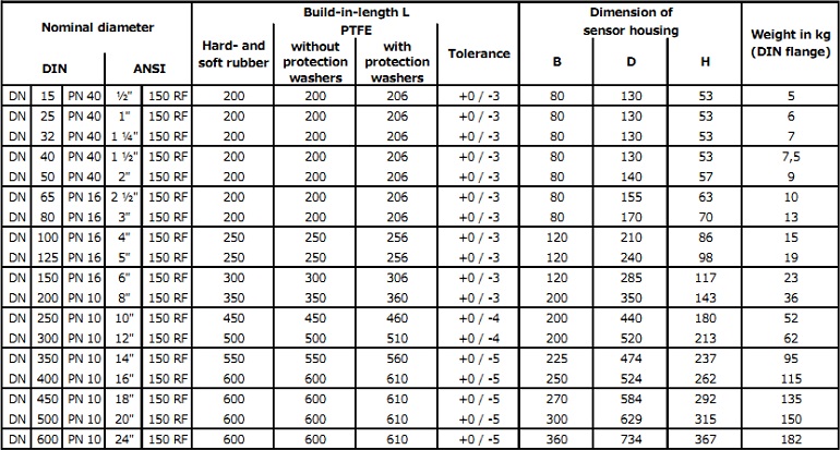
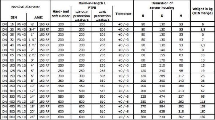
Design Weight
Sensor material : measuring tube Solenoid chamber Flange
Lining of measuring pipe
Electrodes Material
Design
Electrode sealing (rubber lining) |
Welde steel housing see page 5
Stainless steel mat. No. 1.4301 (or better) Steel, stainless steel optional ·        Steel ·        Stainless steel ·        Special materials ·        Hard rubber/soft rubber ·        PTFE (Teflon)
Mat. No. 1.4571 (Standard) Hastelloy C4 Titanium Tantalum Platinum Monel Mat. No. 1.4571 flat electrodes other point-plane electrodes Viton (standard) EPDM Klrez
|
| Wiring             2 x M 16 x 1,5 / 2 x 1/2″ NPT | |
Informayion for sensors with PTFE lining
The mag-flux A sensor with PTFE lining is protected using a protective disc. In order to avoid formation of a vacuum,the sensor should be installed at the lowest point of the pipeline. Do not remove or demage the bead of the lining along the flanges.
Information for sensors with soft rubber lining
Sensors with soft rubber/neoprene lining are only available from nominal diameter DN 25mm (1″).
Selection on minimal diameter
The flow depends on the flow rate and the nominal diameter DN of the flow measuring device (see system information mag-flux for magnetic inductive flow measurements).
Accessories
Sensor cable
Typically, the induced signal voltage of the measuring media can be several pV or mV. the transmitter can only process these minute signal noise-free interfering signals are avoided; these nclude: signals intefering with the power frequency, signals wich are caused by vibrations in the pipeline or in the cable run, or signal caused by strong magnetic flieds in the vicinity. In this case, sufficient shielding must be provided and, if a separate design is chosen, the signal cables must be affixed firmly.
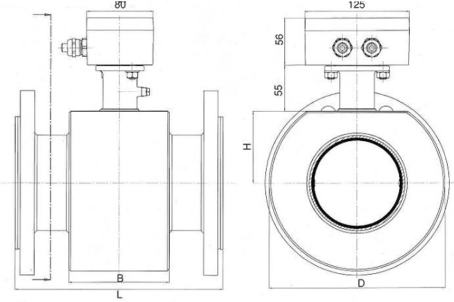
Dimensions (remote version)