
Turbine Flow meters
Turbine Flow meters
 FEATURES
• One moving part
• Low friction jewel bearings
• Field repairable without removal from the line
• Choice of materials for chemical compatibility
• Variety of displays and control
APPLICATIONS
• Water treatment
• Wastewater treatment
• Cooling water monitoring
• Industrial fluid control
GENERAL INFORMATION
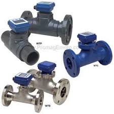
This unique system of 2″ to 8″ Seametrics turbine flow meters uses just one moving part, a precision helical rotor. Rotation of the rotor is electronically detected and processed. The high-quality jewel bearings and polished zirconia ceramic shafts minimize friction while providing long wear life in non-lubricating fluids. The entire rotor assembly can be easily removed for field service without removing the meter from the pipe.
WTP bodies are fabricated from Schedule 80 PVC fittings, WTC bodies from carbon steel tubing, and WTS bodies (available as special order) from stainless steel tubing. The turbine insert on WTC and WTS meters is machined from a stainless steel casting. The WTP turbine insert is machined from a solid piece of PVC (polypro in 2” size). Turbine rotors on all models are Kynar (PVDF).
WT flow meters can be ordered with various output options. The basic model (100) comes with pulse output only. An electronic display (Seametrics FT420) is mounted on the 101 model to display flow rate and total (resettable or non-resettable), and provide a programmable pulse or 4-20 mA output. Other electronics options include a blind 4-20 mA transmitter (AO55) on the 102 model and a battery-powered (FT415) rate/totalizer plus pulse output for applications that lack power (104 model). All of these controls/displays can be mounted on the meter or remotely mounted on a wall or panel up to 2,000 feet away. WTSeries flow meters are compatible for use with most other remote-mount Seametrics displays and controls as well.
Turbine Flow Meter Model :
1. WTS Turbine Flow Meter ( Stainless Steel Turbine Flow Meter )
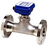 Stainless-steel body turbine flow meter
In-line, individually-calibrated turbine meter maximizes accuracy
Turbine rotor is the only moving part, optimizing low-flow performance
Solid-state pickup
Electronic register can be meter-mounted or remote
Available with blind pulse or 4-20 mA output
Lightweight, corrosion-resistant 304SS (or optional 316SS) body
Flanges standard 3″ and above (2″ has female NPT threads)
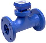
2. WTP Turbine Flow Meter ( PVC Turbine Flow Meter )
 PVC-body turbine flow meter
In-line, individually-calibrated turbine flow meter maximizes accuracy
Turbine rotor is the only moving part, optimizing low-flow performance
Solid-state pickup
Electronic register can be meter-mounted or remote
Available with blind pulse or 4-20 mA output
Materials are chemical-resistant
Can be ordered with stub ends (standard) or flanges (optional)
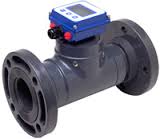
3. WTC Turbine Flow Meter ( Carbon Steel Turbine Flow Meter )
 In-line, individually-calibrated turbine flow meter maximizes accuracy
Turbine rotor is the only moving part, optimizing low-flow performance
Solid-state pickup
Electronic register can be meter-mounted or remote
Available with blind pulse or 4-20 mA output
Heavy-duty, fabricated steel body with shopcoat
Flanges standard 3″ and above (2″ has female NPT threads)
SPECIFICATION Â Â Â Â Â Â Â Â Â Â Â Â WTC Â Â Â Â Â Â Â Â Â Â Â Â Â Â Â Â Â Â Â WTP Â Â Â Â Â Â Â Â Â Â Â Â Â Â Â Â Â Â Â Â WTS
| Pipe Sizes | 2”, 3”, 4”, 6” | 2”, 3”, 4”, 6”, 8” | 2”, 3”, 4”, 6”, 8” | |||||||||||
| Materials                Meter Body | PVC Schedule 80 fittings | PVC Schedule 80 fittings | 304 Stainless steel (316 SS optional | |||||||||||
| Turbine Insert | PVC | CF8M cast stainless | CF8M cast stainless | |||||||||||
| Rotor | Kynar (PVDF) | Kynar (PVDF) | Kynar (PVDF) | |||||||||||
| Shaft | Zirconia ceramic 3”-6” | Zirconia ceramic 3”-8” | Zirconia ceramic 3”-8” | |||||||||||
| Shaft | Tungsten Carbide 2” | Tungsten Carbide 2” | Tungsten Carbide 2” | |||||||||||
| Bearings | Sapphire journal, ruby endstone | Sapphire journal, ruby endstone | Sapphire journal, ruby endstone | |||||||||||
| Cable | #22 AWG, 2000’ max | #22 AWG, 2000’ max | #22 AWG, 2000’ max | |||||||||||
| Flanges | Optional (See Dimensions) | 150 lb. drilling (3-8” only) | 150 lb. drilling (3-8” only) | |||||||||||
| Maximum Pressure | 150 psi @ 75Ëš F
(10 bar @ 24Ëš C) (see chart) |
200 psi (14 bar) | 200 psi (14 bar) | |||||||||||
| Maximum Temperature | 120Ëš F (50Ëš C) (see chart) | 200Ëš F (93Ëš C) | 200Ëš F (93Ëš C) | |||||||||||
| Accuracy                            3”-8” | +/- 1% of full scale | +/- 1% of full scale | +/- 1% of full scale | |||||||||||
|                                                 2” | +/- 2.5% of full scale | +/- 2.5% of full scale | +/- 2.5% of full scale | |||||||||||
| Flow Range (GPM) | 2” | 3” | 4” | 6” | 2” | 3’’ | 4’’ | 6’’ | 8’’ | 2’’ | 3’’ | 4’’ | 6’’ | 8’’ |
| Minimum | 2 | 3 | 6 | 12 | 2 | 3 | 6 | 12 | 30 | 2 | 3 | 6 | 12 | 30 |
| maximum | 150 | 400 | 600 | 1200 | 150 | 400 | 600 | 1200 | 3000 | 150 | 400 | 600 | 1200 | 3000 |
ELECTRONIC OPTIONS SPECIFICATION
| WT100 (3-wire, Pulse Output Only) | Â Â Â WT102 (2-wire, Blind 4-20 Transmitter) (e.g. AO55) | |||
| Power | 6-24 Vdc | Power | 24 – 36 Vdc (isolated) | |
| Pulse Output | 0-160 pulse/second current sinking | Analog Output | 4-20 mA loop | |
| Â | Response Time | 2-60 seconds, 90% of full scale
(depends on input averaging) |
||
| WT101 (4-wire, Powered Rate/Totalizer) (e.g. FT420) | Â Â Â WT104 (Battery-powered Rate/Totalizer) (e.g. FT415) | |||
| Power | 12-32 Vdc (for 4 mA DC min);
24-32 Vdc (for accuracy of 4-20 mA loop) |
Power | 3.6 Vdc Lithium battery
replaceable, 3-5 year life |
|
| Rate | 6-digit autorange | Rate | 6-digit auto range | |
| Total | 8-digit | Total | 8-digit | |
| Memory | Non-volatile (no battery needed) | Pulse Output | 0.1 second open collector (scaled);
0-75 pulse/second passthrough (unscaled); High alarm or low alarm |
|
| Pulse Output | 0.1 second open collector (scaled);
0-75 pulse/second passthrough (unscaled); High alarm or low alarm |
 | ||
| Analog Output | 4-20 mA loop (24-32 Vdc required) | Â | ||